

Interconnection networks - an introduction
Part 2: Data centre switching primer to provide some background as to what Rockley Photonics is doing.
 Source: Jonah D. Friedman
If moving information between locations is the basis of communications, then interconnection networks represent an important subcategory.
The classic textbook, Principles and Practices of Interconnection Networks by Dally and Towles, defines interconnection networks as a way to transport data between sub-systems of a digital system.
The digital system may be a multi-core processor with the interconnect network used to link the on-chip CPU cores. Since the latest processors can have as many as 100 cores, designing such a network is a significant undertaking.
Equally, the digital system can be on a far larger scale: servers and storage in a data centre. Here the interconnection network may need to link as many as 100,000 servers, as well as the servers to storage.
The number of servers being connected in the data centre continues to grow.
“The market simply demands you have more servers,” says Andrew Rickman, chairman and CEO of UK start-up Rockley Photonics. “You can’t keep up with demand simply with the advantage of [processors and] Moore’s law; you simply need more servers.”
Scaling switches
To understand why networking complexity grows exponentially rather than linearly with server count, a simple switch scaling example is used.
With the 4-port switch shown in Figure 1 it is assumed that each port can connect to the any of the other three ports. The 4-port switch is also non-blocking: if Port 1 is connected to Port 3, then the remaining input and output can also be used without affecting the link between ports 1 and 3. So, if four servers are connected to the ports, each can talk to any other server as shown in Figure 1.
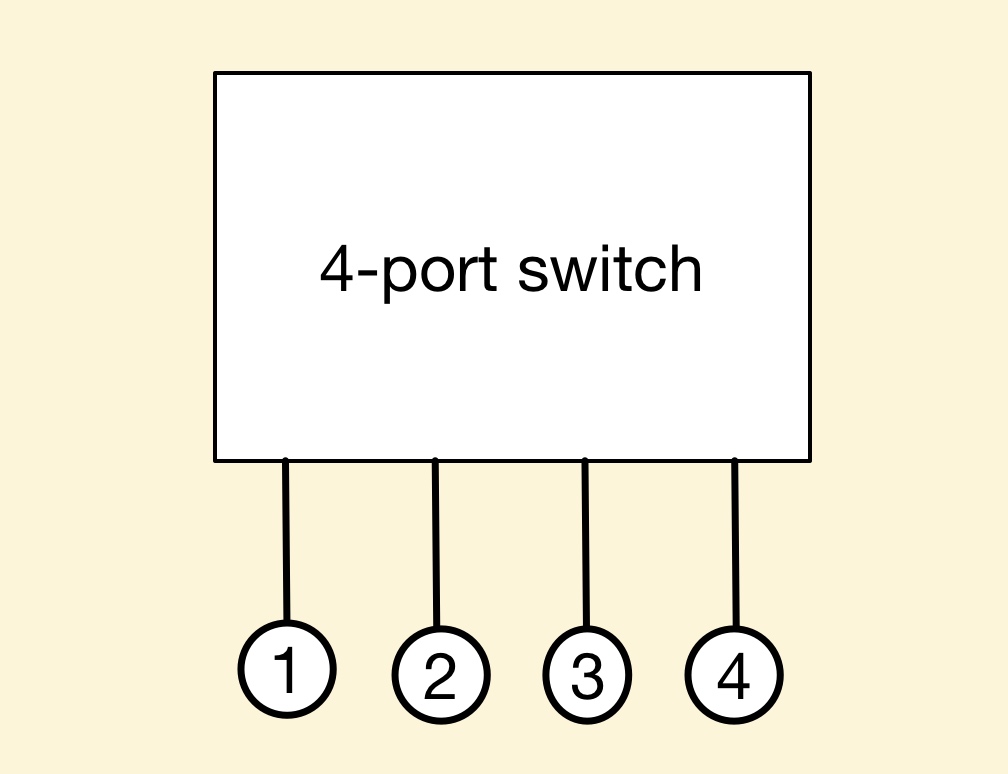 Figure 1: A 4-port switch. Source: Gazettabyte, Arista Networks
But once five or more servers need to be connected, things get more complicated. To double the size to create an 8-port switch, several 4-port basic building switches are needed, creating a more complex two-stage switching arrangement (Figure 2).
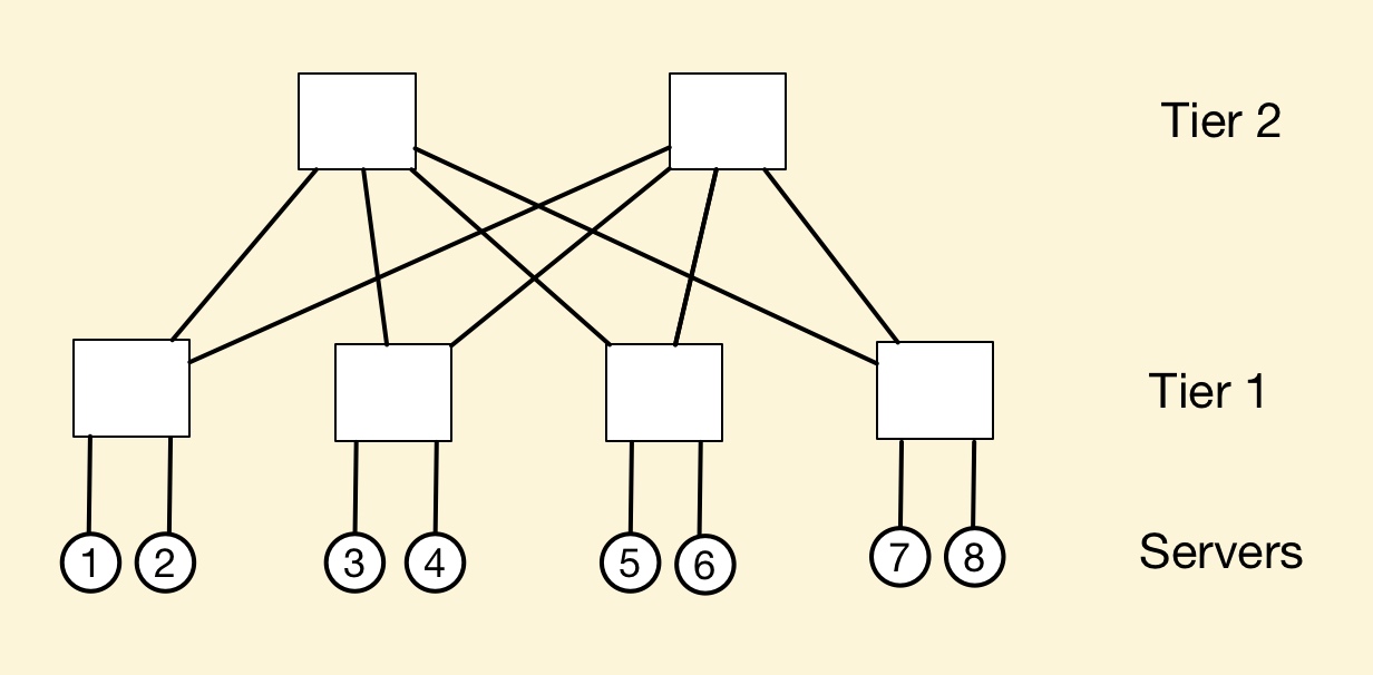 Figure 2: An 8-port switch made up of 4-port switch building blocks. Source: Gazettabyte, Arista Networks.
Indeed the complexity increases non-linearly. Instead of one 4-port building block switch, six are needed for a switch with twice the number of ports, with a total of eight interconnections (number of second tier switches multiplied by the number of first tier switches).
Doubling the number of effective ports to create a 16-port switch and the complexity more than doubles again: now three tiers of switching is needed, 20 4-port switches and 32 interconnections (See Table 1).
 Table 1: How the number of 4-port building block switches and interconnects grow as the number of switch ports keep doubling. Source: Gazettabyte and Arista Networks.
The exponential growth in switches and interconnections is also plotted in Figure 3.
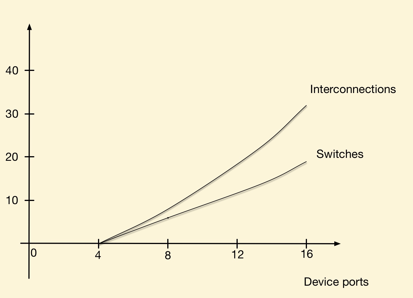 Figure 3: The exponential growth in N-sized switches and interconnects as the switch size grows to 2N, 4N etc. In this example N=4. Source: Gazettabyte, Arista Networks.
This exponential growth in complexity explains Rockley Photonics’ goal to use silicon photonics to make a larger basic building block. Not only would this reduce the number of switches and tiers needed for the overall interconnection network but allow larger number of servers to be connected.
Rockley believes its silicon photonics-based switch will not only improve scaling but also reduce the size and power consumption of the overall interconnection network.
The start-up also claims that its silicon photonics switch will scale with Moore’s law, doubling its data capacity every two years. In contrast, the data capacity of existing switch ASICs do not scale with Moore’s law, it says. However the company has still to launch its product and has yet to discuss its design.
Data centre switching
In the data centre, a common switching arrangement used to interconnect servers is the leaf-and-spine architecture. A ‘leaf’ is typically a top-of-rack switch while the ‘spine’ is a larger capacity switch.
A top-of-rack switch typically uses 10 gigabit links to connect to the servers. The connection between the leaf and spine is typically a higher capacity link - 40 or 100 gigabit. A common arrangement is to adopt a 3:1 oversubscription - the total input capacity to the leaf switch is 3x that of its output stream.
To illustrate the point with numbers, a 640 gigabit top-of-rack switch is assumed, 480 gigabit (or 48 x10 Gig) capacity used to connect the servers and 160 gigabit (4 x 40 Gig) to link the top-of-rack switch to the spine switches.
In the example shown (Figure 4) there are 32 leaf and four spine switches connecting a total of 1,536 servers.
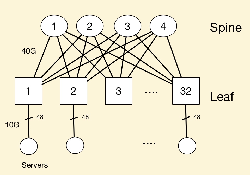 Figure 4: An example to show the principles of a leaf and spine architecture in the data centre. Source: Gazettabyte
In a data centre with 100,000 servers, clearly a more complicated interconnection scheme involving multiple leaf and spine clusters is required.
Arista Network’s White Paper details data centre switching and leaf-and-spine arrangements, while Facebook published a blog (and video) discussing just how complex an interconnection network can be (see Figure 5).
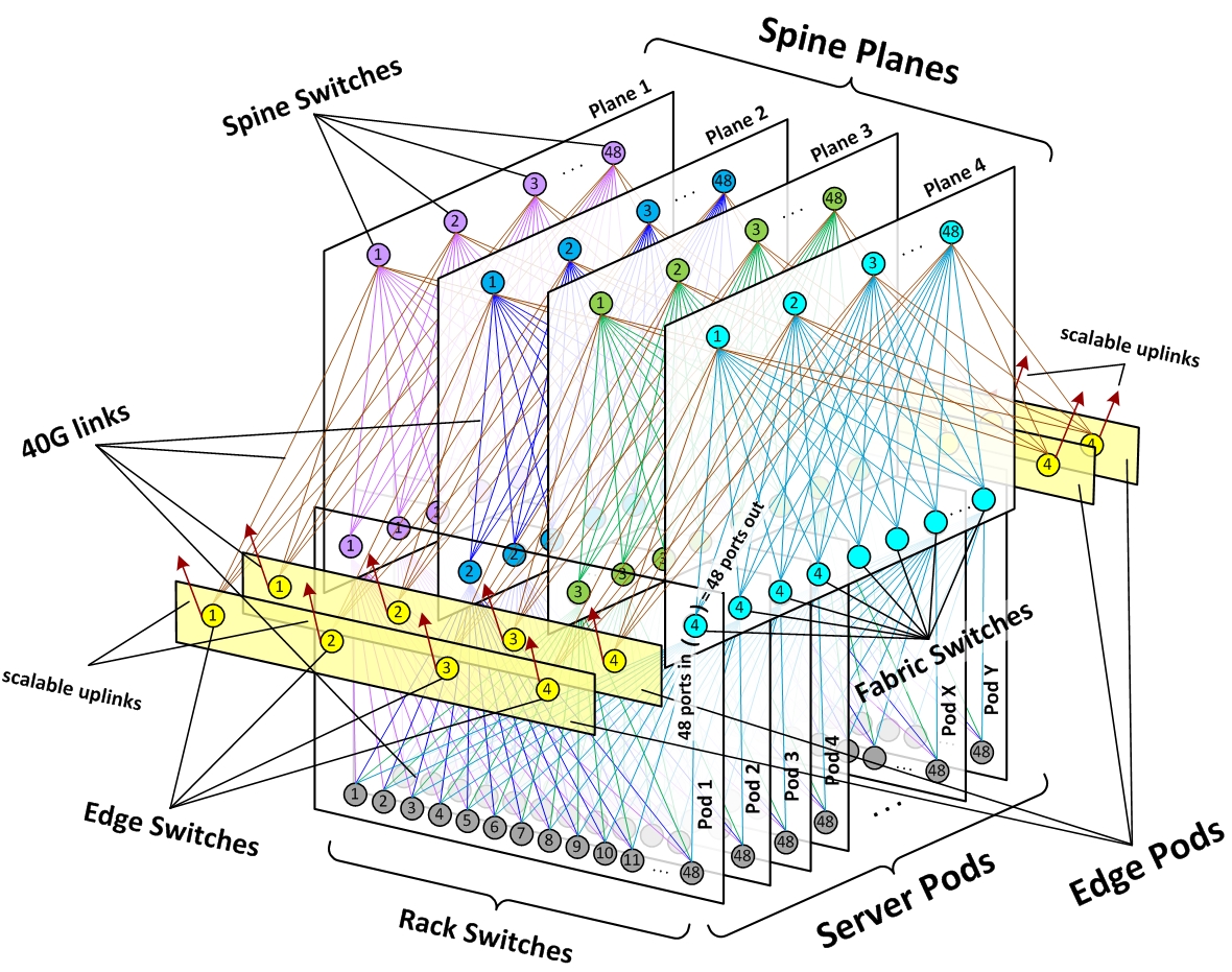 Figure 5: How multiple leaf and spines can be connected in a large scale data centre. Source: Facebook
 Post a Comment
Reader Comments